|
POWER Distribution
Ok,
now you're turning it ON and OFF, the next Job is Getting Power round
the panel to feed all the switches/LED's. This is how I did
it.
I broke it down
into two sections, the POWER
DISTRIBUTION
and the BUS. POWER
DISTRIBUTION is the most complicated to achieve because it has
to follow a given sequence of what lights up when this happens
or that system is turned off. So we'll deal with this first.
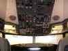
 SYSTEM Switching SYSTEM Switching
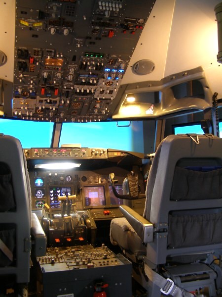
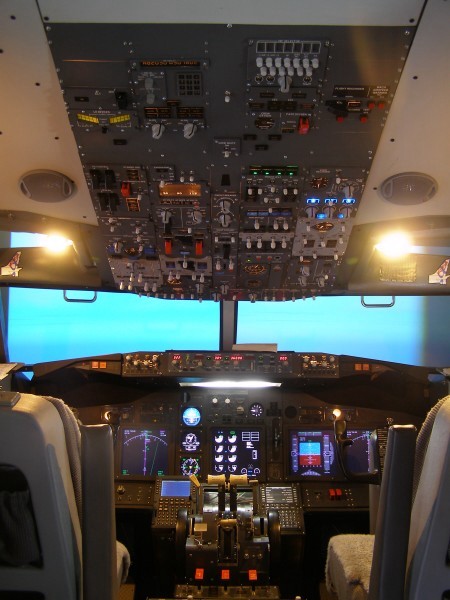
My aim is to make it realistic, yet as simple as possible. So there
has to be a compromise somewhere. There are several sources of
power available to the crew of a 737 aircraft. Main sources being
Battery, Ground Power, APU and Engine Generators. So to simplify
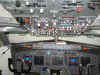
matters, i decided to use a rotary switch on the meter panel to
distribute my 5v to the various systems. There is a Switch
position here for both ENG Gens APU and GND PWR,
so let's start here. I'm hoping to automate this but I just
don't seem to be able to find the time to sit down and get
playing with relays and switches. But watch this space.
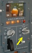
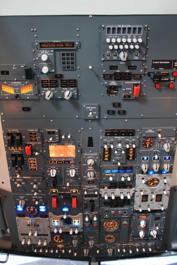
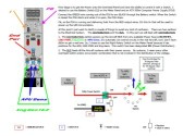
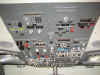
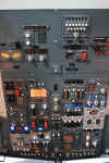
 GROUND
POWER When Ground Power is available, the selector is
turned to the GND PWR position on the Meter
Panel. 5v is routed to the Ground Power
Available Switch (Lighting the BLUE GND PWR Avail Annunciator). Pushed
Down, the switch then routes the 5v to the Distribution BUS (See
Left Document) GROUND
POWER When Ground Power is available, the selector is
turned to the GND PWR position on the Meter
Panel. 5v is routed to the Ground Power
Available Switch (Lighting the BLUE GND PWR Avail Annunciator). Pushed
Down, the switch then routes the 5v to the Distribution BUS (See
Left Document)
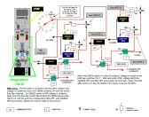
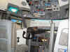
APU After starting the APU, the
selector knob is turned to the APU position. Power is routed to
the APU Generator Switches which control the Blue APU Gen annunciator
and deliver power to the BUS based on the position of the
switches..
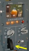
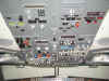
ENG GENS
After Eng start, turning the Power
Distribution switch to either of the Eng Gen positions routes
the voltage tru the DRIVE switches to the Eng Gen
Switches. ENG Gen switches OFF, Source Off and Eng Gen Off
annunciators are illuminated. Eng Gen switches ON, voltage is
delivered to the BUS.
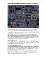
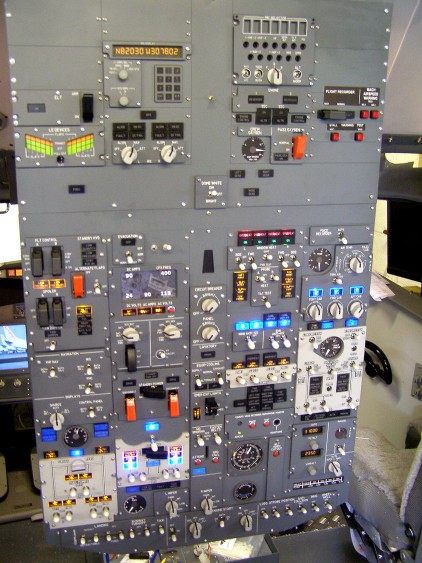
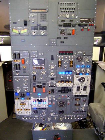
DISTRIBUTION
CIRCUIT DIAGRAM
PDF Click one
of the pictures above to
download the Distribution Circuit Diagram
PDF
file for a better insight into how it all comes together. The
Overhead NOTES are HERE
The
BUS.
I've managed to get to start the BUS document, so i thought i'd
upload what i have so far. If nothing else, it will give
you the general idea of what is going on and how to start
connecting your switches.
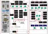 **
Added March 16th 2009.
Here's the First
few pages of the BUS circuit. I'm already on with the next
few pages, but several people have been on at me for the
document. This is the most complex part of the overhead
and it will give you a good idea of how i am doing things and
getting the circuit to work. As i complete the next
section i'll upload it. But as always, it's my hobby not
my job :o)) **
Added March 16th 2009.
Here's the First
few pages of the BUS circuit. I'm already on with the next
few pages, but several people have been on at me for the
document. This is the most complex part of the overhead
and it will give you a good idea of how i am doing things and
getting the circuit to work. As i complete the next
section i'll upload it. But as always, it's my hobby not
my job :o))
SWITCH
TYPES
 Here
we go....this is where it gets serious. You have to have a PLAN.
Don't go blindly off soldering bits of wire to switches and make
it up as you go along. That is going to end in frustration and
tears. Think about what Overhead Panel Switches you want
to operate and HOW. What switch is going to be
connected to what interface. How does that
interface respond. Is it a joystick controller or a
Keyboard Emulator or a dedicated piece of I/O hardware? Here
we go....this is where it gets serious. You have to have a PLAN.
Don't go blindly off soldering bits of wire to switches and make
it up as you go along. That is going to end in frustration and
tears. Think about what Overhead Panel Switches you want
to operate and HOW. What switch is going to be
connected to what interface. How does that
interface respond. Is it a joystick controller or a
Keyboard Emulator or a dedicated piece of I/O hardware?
This is where you now have to formulate your plan because no two
cockpits are identical and as we suffer from a distinct lack of
standards in this hobby, everybody manufacturing a hardware
interface system is going off in their own direction leaving
most of us bewildered. You have to make a decision whether
you are going to go with one of the commercial solutions or are
you going to make it yourself. Bad things happen if you
make the wrong decision. By doing it myself, support
lives in the same house as me :o))
 On
the left is a link to the types of switches that are readily
available. These are what i have used in my overhead panel. On
the left is a link to the types of switches that are readily
available. These are what i have used in my overhead panel.
 Type 1
is a simple Push to Make Switch
making it ideal for Attendant and Guard Call or the Test Button
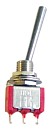
on the AirCon Panel. Type
2 is again a simple ON/OFF
Toggle Switch which can be used for any switch function that
does not require the control of the voltage at the same time
(e.g. Landing Lights, Taxi Lights, Anti Collision and Nav
Lights. Also used for the Recirc fans.
Type 3 is a Two Pole Switch.
These are available as ON/ON, ON/OFF/ON and as Momentary
Switches (ON)/OFF/(ON). Ideal for lots of applications
because they connect two different continuity circuits in one
switch. The Momentary switch lends itself to the No Smoking and
Seatbelts application because they are spring loaded to centre
and no power needs to be controlled. Type 1
is a simple Push to Make Switch
making it ideal for Attendant and Guard Call or the Test Button
on the AirCon Panel. Type
2 is again a simple ON/OFF
Toggle Switch which can be used for any switch function that
does not require the control of the voltage at the same time
(e.g. Landing Lights, Taxi Lights, Anti Collision and Nav
Lights. Also used for the Recirc fans.
Type 3 is a Two Pole Switch.
These are available as ON/ON, ON/OFF/ON and as Momentary
Switches (ON)/OFF/(ON). Ideal for lots of applications
because they connect two different continuity circuits in one
switch. The Momentary switch lends itself to the No Smoking and
Seatbelts application because they are spring loaded to centre
and no power needs to be controlled.
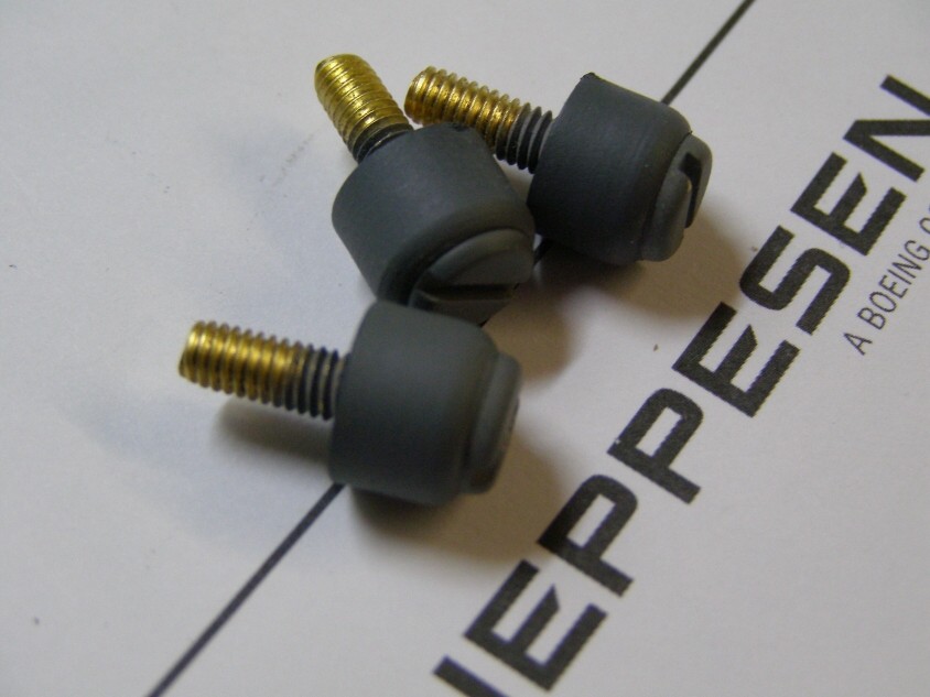
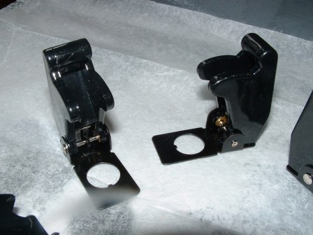
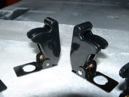
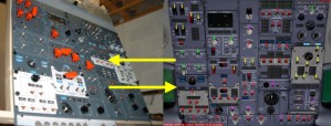
 Type 4
Now we are cooking :o). This is a Double Pole, Double
Terminal Switch. It's basically two seperate switches in
one housing. This now allows us to control the voltage on
one side and the input to our interface device on the other.
Ideal for use on every switch that is used to input to the
interface card and control voltage whether it's for routing or
to light an annunciator. Type 4
Now we are cooking :o). This is a Double Pole, Double
Terminal Switch. It's basically two seperate switches in
one housing. This now allows us to control the voltage on
one side and the input to our interface device on the other.
Ideal for use on every switch that is used to input to the
interface card and control voltage whether it's for routing or
to light an annunciator.
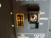
The above example is the Eng Gen switch. One side signals our
interface to action something (in this case the Joystick
Controller) and the other side switches the 5v to the Eng Gen
Off Annunciator.
For More Information on What Switch To Use and How To Connect
It, Download the Switchmap Document in the left column.


|
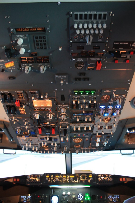
Controlling
the PMDG Overhead With Hardware
May 2008, Everything has
changed! Pete Dowson has just released his FSUIPC
v3.81 which includes a function on Mouse Macro's. Pete uses
a routine called 'Mousetrapping' which reads your action with the
mouse and allows you to record that action as a code and not as a
mouseclick.
It then follows that that action can be applied to almost any switch or gauge
WITHOUT IT BEING IN VIEW :o) So, you do not
have to open the PMDG OVERHEAD PANEL to action the switches (nor the
Radio Panel or MIP either). You
have to have a Registered version of FSUIPC to do this,
but it's great value for money. By registering, you not only keep Pete
Dowson developing, but it also means he will continue to support you.
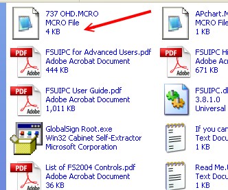
 Included in the Downloaded FSUIPC.zip is a file called 737 OHD.mcro.
What Pete has done is map all the switch actions on the PMDG Overhead
and create macro's for them. When you copy the .dll file
to your FS/Modules folder, you take this .mcro file as well and when
FS/PMDG is started all the 737 OHD
Included in the Downloaded FSUIPC.zip is a file called 737 OHD.mcro.
What Pete has done is map all the switch actions on the PMDG Overhead
and create macro's for them. When you copy the .dll file
to your FS/Modules folder, you take this .mcro file as well and when
FS/PMDG is started all the 737 OHD 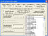 macro's are available to you in the
Button Press and Keystroke Dropdown Menu's - BRILLIANT ! macro's are available to you in the
Button Press and Keystroke Dropdown Menu's - BRILLIANT !
But it doesn't end there. Pete has also included the ability for
us to write our own macro's as well, but that's another story for
another day :o))
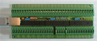 CONNECTING
YOUR SWITCHES
Now everybody knows i'm a great fan of Leo Bodnar's BU0836 family of
Joystick Control Cards. So it was a natural choice for me to
connect up the first 32 switch actions thru the new BU0836X board.
What this board does is make Windows think it's a Joystick with 8
analogue Axes and 32 buttons (bit like a 'barebones' SAITEK X45) which
can be tested in the Game Controllers Page in the Control Panel just
like any other Joystick.
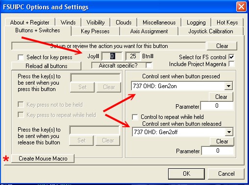
So by connecting switches and pushbuttons to the numbered button
inputs on the card, upto 32 button presses can be sent in.
Then of course FSUIPC is able to action one command when the button is
pressed and another when the button is released giving us two actions
on one switch if we need it.
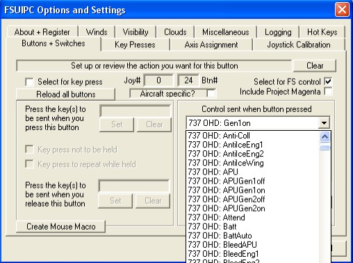
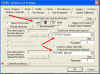 Here's
an example, the Eng1 Gen Switch. Here's
an example, the Eng1 Gen Switch.
Connect a simple On/Off Toggle Switch to any input on your controller
card (it doesn't have to be a BU0836X) and start FS with the PMDG
737NG loaded. Now open FSUIPC and go to the Buttons &
Switches page and turn the switch ON. FSUIPC will see the
switch action and identify it as Joy#, Button#. Once your input
has been recognised, tick the 'FS Control' box and then select the
'737 OHD: Gen1 On' item in the dropdown menu for when the button is
pressed and the '737 OHD: Gen1 Off' item for 'when the button is
released'. You now have two actions from one switch, go on
try it. Good isn't it.
Here's another example, the Seatbelts Switch.
What
we have here is a different type of switching. It is a two
action on and off switch which is spring loaded to centre. So for this
type of switch, i needed to use two inputs. One for the UP and
one for the DOWN (the No Smoking Switch is the same). So i used two
button inputs and shared a common ground connection to give me the two
inputs i needed. Then it's off to FSUIPC to identify the
input and assign the action (as previously).
 And
finally for my mate Alan Watson (who has a thing about this), a final
example is the Attendant Call Button. A simple
push button that when pressed emits the famous Boeing Chime.
Connect a simple push to make Pushbutton to one input on your
controller and assign it in FSUIPC to the '737 OHD: Attend' item.
Simple. And
finally for my mate Alan Watson (who has a thing about this), a final
example is the Attendant Call Button. A simple
push button that when pressed emits the famous Boeing Chime.
Connect a simple push to make Pushbutton to one input on your
controller and assign it in FSUIPC to the '737 OHD: Attend' item.
Simple.
USING
ENCODERS
Leo has now upgraded the BU0836 family of controllers to accept inputs
from Rotary Encoders, so it then follows that Inrease/Decrease Rotary
Controls (like FLT ALT and LAND ALT) can now be utilised as
well. If you have purchased a BU0836 card this year, the
firmware will already be in place. You can get the configuration
program to assign inputs on your BU0836 card HERE.
I use two types of encoder for this type of Input, the CTS288
from OPENCOCKPITS and also a cheap Chinese Encoder from Sure
Electronics on e-bay (he's real cheap on LED's as well and his Amber
one's are pretty good too).
Once you have assigned switch pairs in the BU0836_encoders.exe
utility, your card will read the direction of rotation and translate
that into repeated joystick button presses based on direction at one
press per detente. So for repeated presses, simply
continue to turn the encoder.
And there's more:-  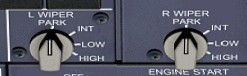
Ok,
so we have most of the controls working, but one or two still give us
a problem. For example the Wipers. How do we accurately
control this type of switch. Read this document for the
solution to the problem.
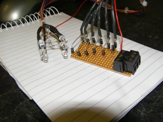
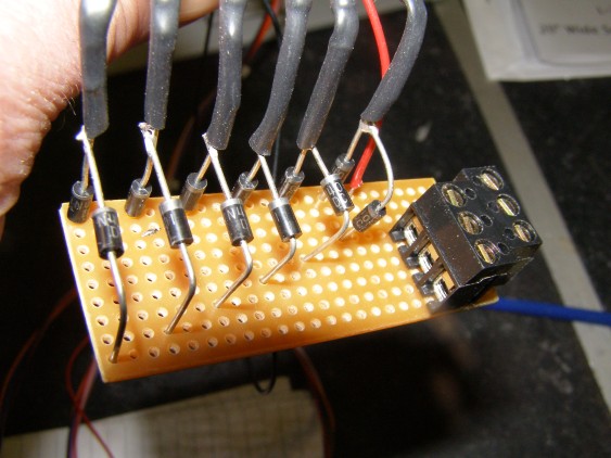
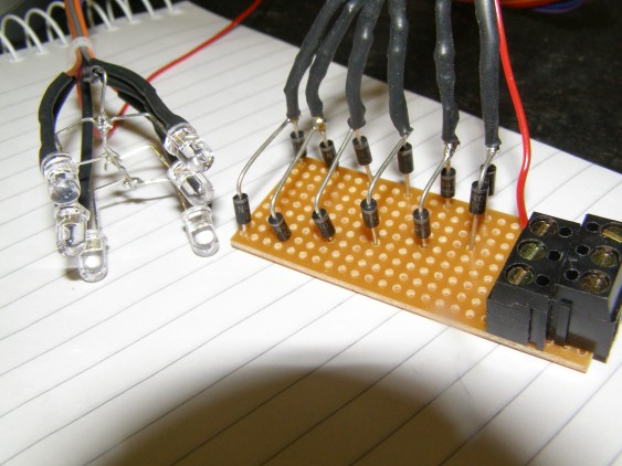
Can also be used on the AUTOBRAKE :o)) MAKING
SIMPLE ENCODERS
Click
an Image To See Some Build Photo's

 e-mail
us e-mail
us
|
 BU0836
Now With Encoder Support
BU0836
Now With Encoder Support