|
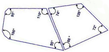 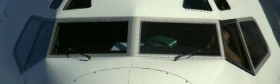
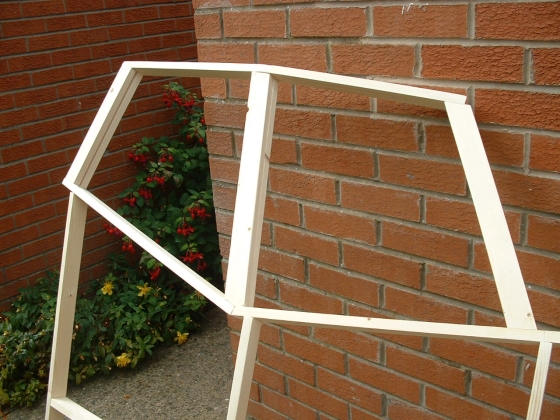
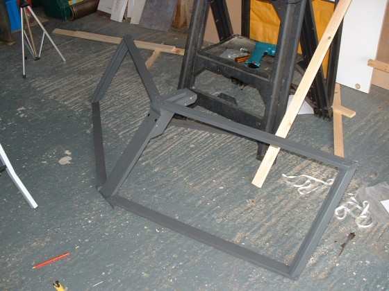
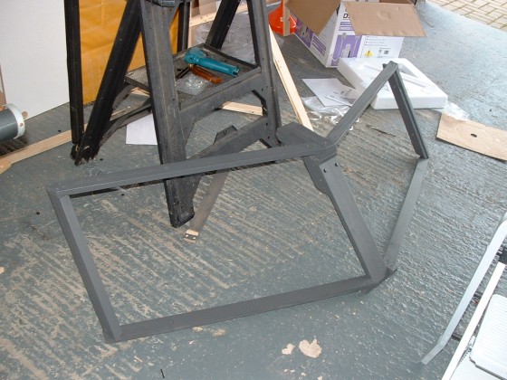
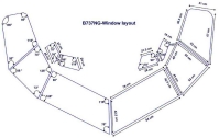
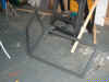
OK, how do you turn this drawing into a B737NG side window
assembly easily? Quite simply you don't. The Windshield assembly is
the most complex part of the shell, so I decided to start there.
What I did was to build a basic frame using straight angles and I will
'round' the two back window angles using the trim sheets.
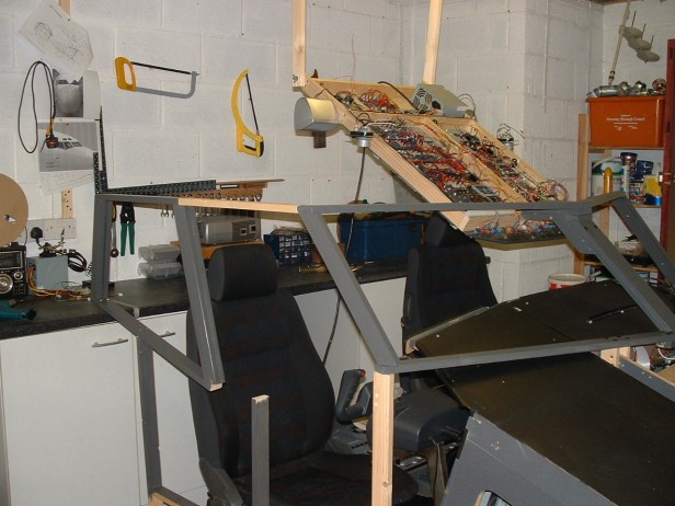
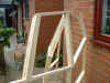
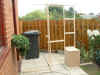
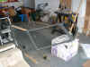
OK, so it's June
2006 and now i
want to build the Shell.
My
original plan was to start at the back and work forward, but I
soon found my plan was 'flawed' because of space constraints, so
i started experimenting with Panel Positions, Angles and getting
the look right. Ok, i admit it looks awful, but the result :o))
The reason I have included 'Warts & All' photo's is this is a
pictorial record and these were the experiments to get it looking
right.

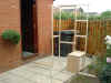


  July
2006, armed with a drawing, a pile of wood and some
tools, I set about trying to create a masterpiece like the one
in the top right image. I
should have gone to the Pub !. If anybody tells you that
building the windshield and side windows of a Boeing 737NG
is easy, don't believe a word of it, it's a B*****D !. I
know, i've been there. But dogged determination and
a will to succeed gets you going in the right direction.
Electronics, Computers and Technology do not defeat me, but I
have to take my hat off to you guys who can master the art of
shaping wood into sophisticated art forms that your wife doesn't
want to light the barbeque with. July
2006, armed with a drawing, a pile of wood and some
tools, I set about trying to create a masterpiece like the one
in the top right image. I
should have gone to the Pub !. If anybody tells you that
building the windshield and side windows of a Boeing 737NG
is easy, don't believe a word of it, it's a B*****D !. I
know, i've been there. But dogged determination and
a will to succeed gets you going in the right direction.
Electronics, Computers and Technology do not defeat me, but I
have to take my hat off to you guys who can master the art of
shaping wood into sophisticated art forms that your wife doesn't
want to light the barbeque with.
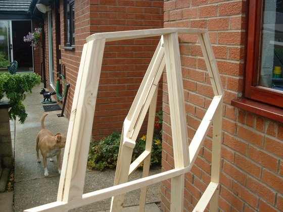
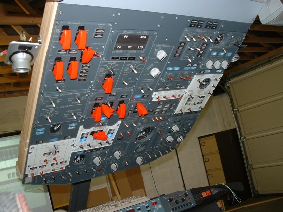
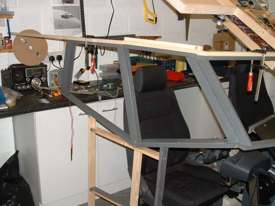
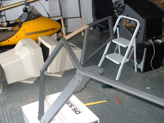
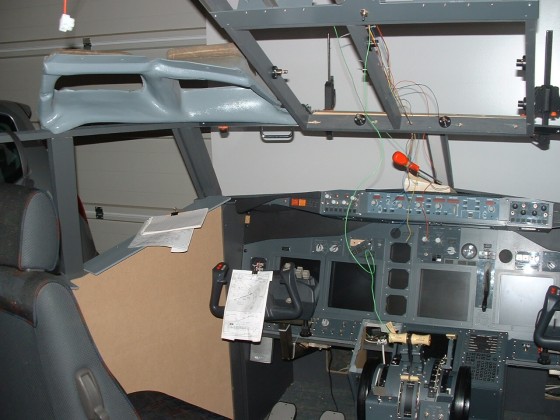
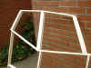
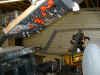
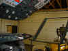
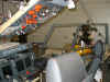
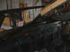
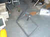
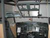
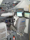
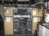
So, two litres of blood later and some swear words i didn't know
i knew, we are getting somewhere. Out of nowhere ,
miraculously has appeared a shape that resembles the two front
windshield panels. I may have been a little
over zealous with the centre support, but it has to support a
lot of weight. And of course there's still time to change the
design.
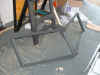

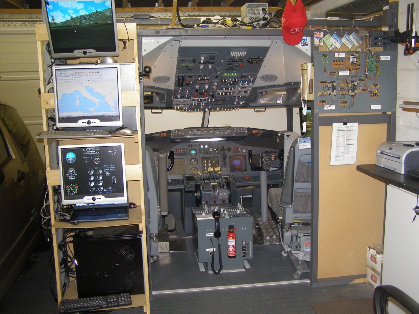
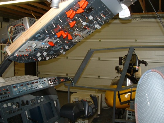
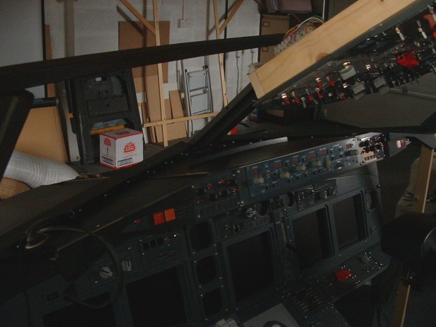
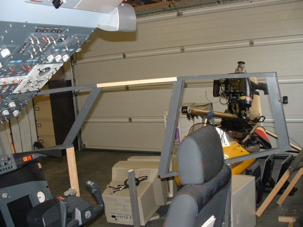
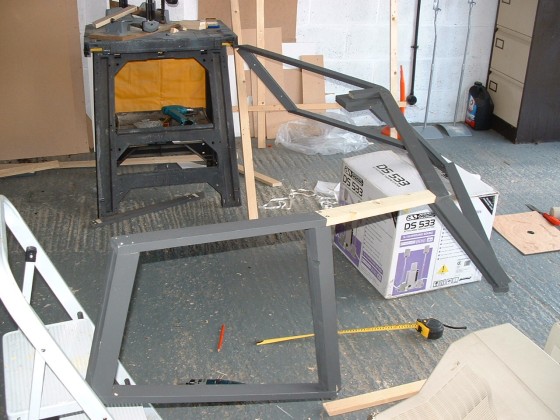
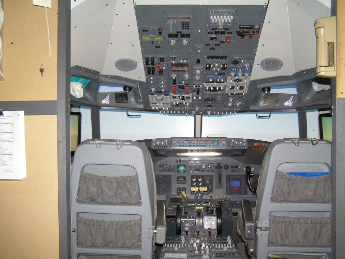
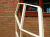
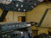
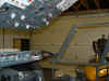
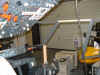
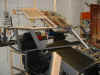
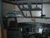
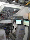
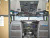
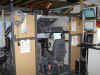
August
2006 Managed
to get the windshield off the ground and mounted. To my surprise
it all actually fits. Now i know the physical dimension of the
Front/Rear Overhead combination and with
these in hand, i made the
frame to hold them and got that fitted. So the basic framework
is starting to take shape. I have one eyebrow window trim, so
this made mating it all up much easier and of course the 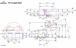 right side is
going to be a mirror image of the left. Now I feel like i'm
getting somewhere. Preparation is everything, so i spent the
rest of the year looking over what drawings i could find to formulate
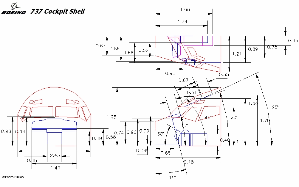
a plan. I based most of my dimensions and angles from the
drawings on this page (more on the TECHNICAL
page) . But A Word Of Advice, you have to
be 'artistic' with the dimensions/angles to get it all to fit together
properly. This took me thru into the spring of 2007. right side is
going to be a mirror image of the left. Now I feel like i'm
getting somewhere. Preparation is everything, so i spent the
rest of the year looking over what drawings i could find to formulate
a plan. I based most of my dimensions and angles from the
drawings on this page (more on the TECHNICAL
page) . But A Word Of Advice, you have to
be 'artistic' with the dimensions/angles to get it all to fit together
properly. This took me thru into the spring of 2007.
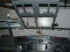
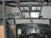
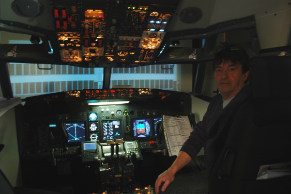
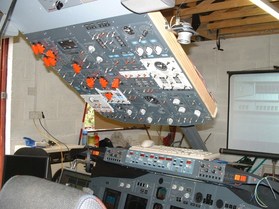
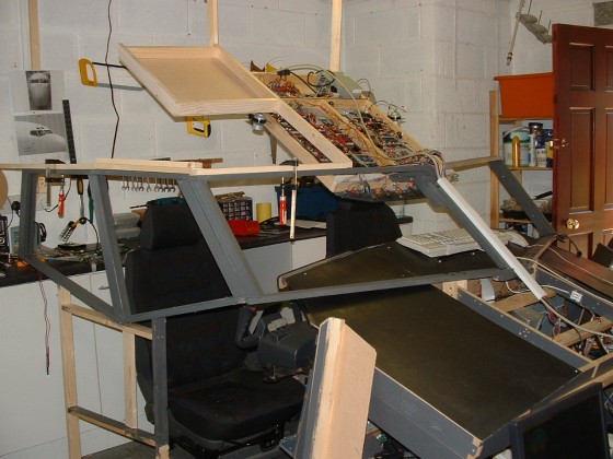
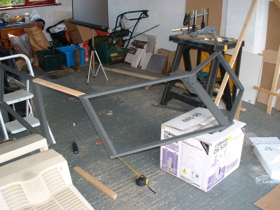
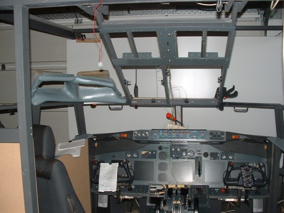
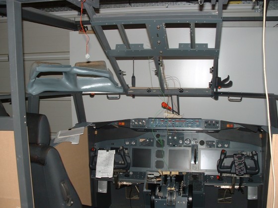
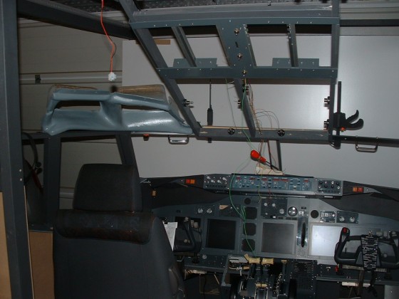
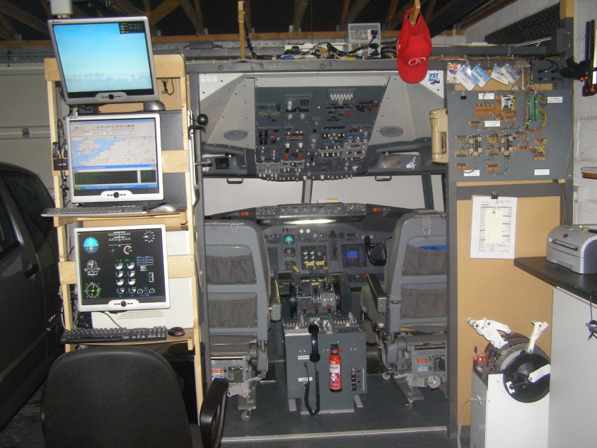
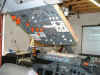
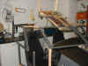
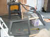
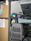
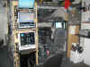
 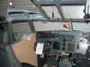  April
2007 The shots
above are basically where we have got to by this time. The basic frame
work is up and I'm just 'tweaking' the last angles and dimensions
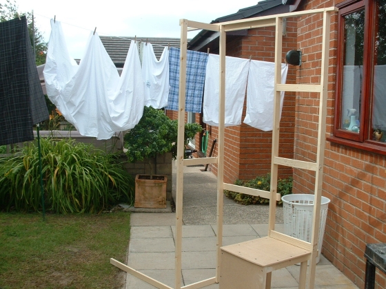
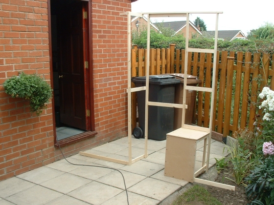
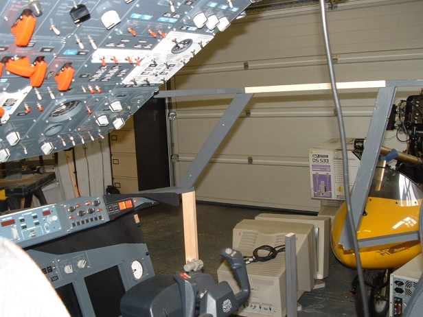
before I screw and glue it all in. At this April
2007 The shots
above are basically where we have got to by this time. The basic frame
work is up and I'm just 'tweaking' the last angles and dimensions
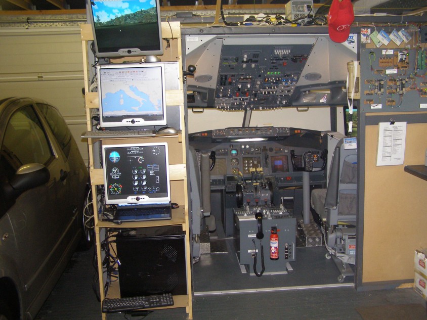
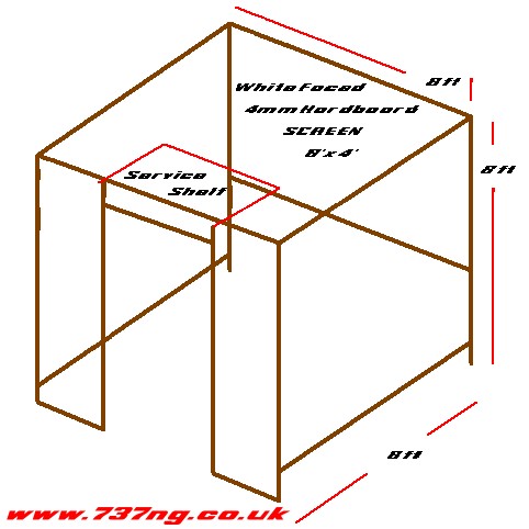
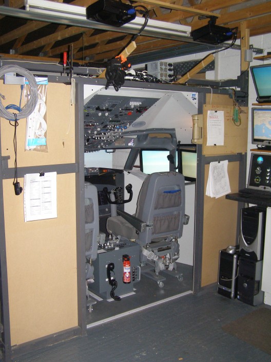
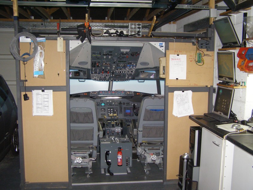
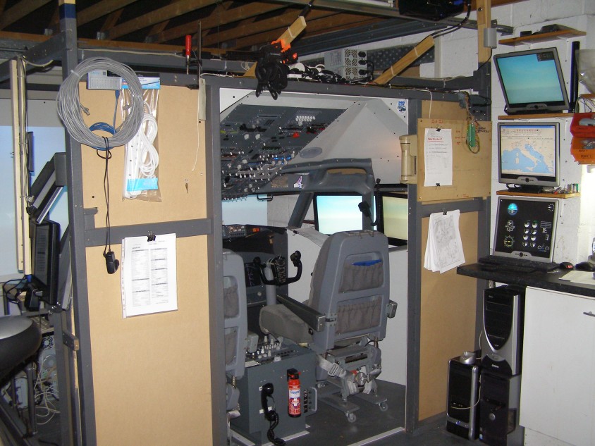
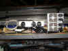
before I screw and glue it all in. At this 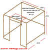 point, I think it's
worth mentioning that a cockpit shell has quite a lot of weight to
to. My best guess is the weight of the wood, cables,
brackets and light fittings is somewhere in the region of
60-70kg. So I decided to build an 8 feet (about 2.5mtrs) outer
frame to give me some support for the weight. Secondly, there
are so many cables and wires, i fitted plastic conduit along the beams
to run the cables in. Great idea, but I still have a plate of
spaghetti behind the frame because i point, I think it's
worth mentioning that a cockpit shell has quite a lot of weight to
to. My best guess is the weight of the wood, cables,
brackets and light fittings is somewhere in the region of
60-70kg. So I decided to build an 8 feet (about 2.5mtrs) outer
frame to give me some support for the weight. Secondly, there
are so many cables and wires, i fitted plastic conduit along the beams
to run the cables in. Great idea, but I still have a plate of
spaghetti behind the frame because i
 can't get in there
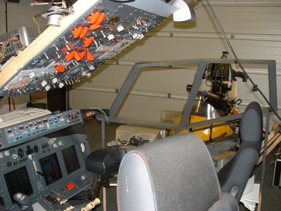
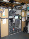
:o)) The frame is constructed from basic wall batten
bolted together. I am constrained to a width slightly over 3mtrs
and a height which is basically the same, so positioning of the
projectors is vital so I can A. Fill the screen and B. not have
cockpit shell parts 'shadow' in the beams. I also have an
electric door on the garage, so I have had to work around the frame
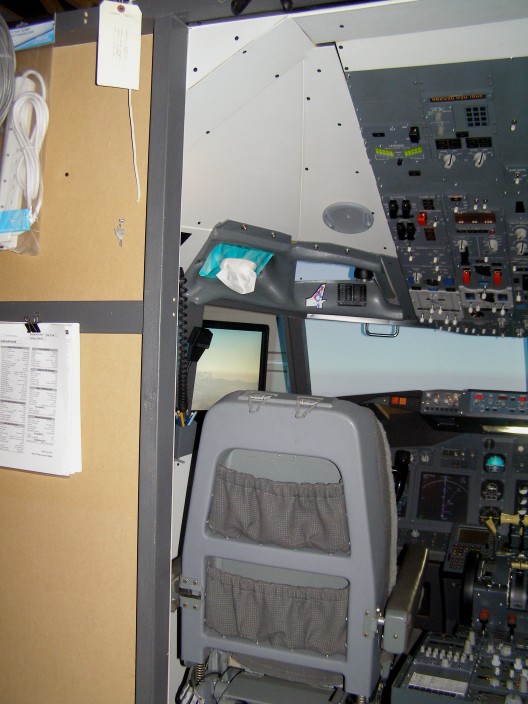
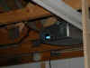
for that as well. Finally, looking above the cockpit
entrance, I can't get in there
:o)) The frame is constructed from basic wall batten
bolted together. I am constrained to a width slightly over 3mtrs
and a height which is basically the same, so positioning of the
projectors is vital so I can A. Fill the screen and B. not have
cockpit shell parts 'shadow' in the beams. I also have an
electric door on the garage, so I have had to work around the frame
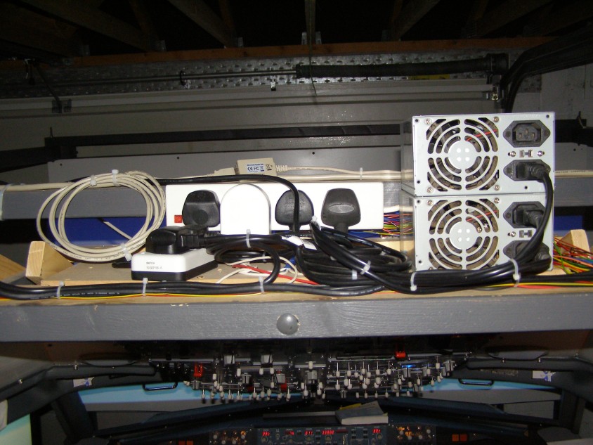
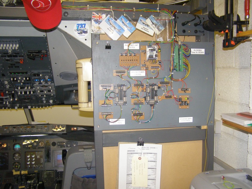
for that as well. Finally, looking above the cockpit
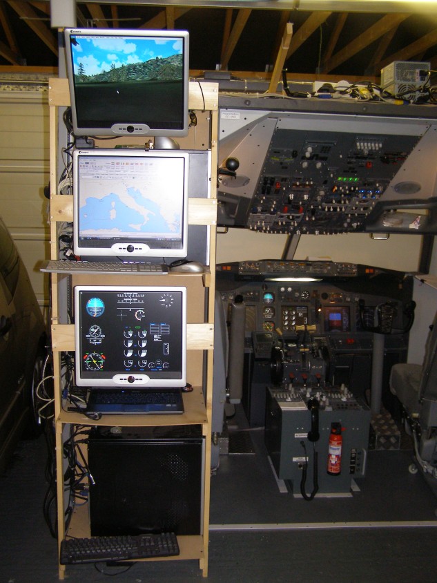
entrance, I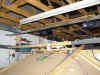 have built a 'Services Shelf' to supply Mains Power and to
house the
Power Supply Units for 12v and 5v d.c. distribution to the
Overhead Panel and MIP. have built a 'Services Shelf' to supply Mains Power and to
house the
Power Supply Units for 12v and 5v d.c. distribution to the
Overhead Panel and MIP.
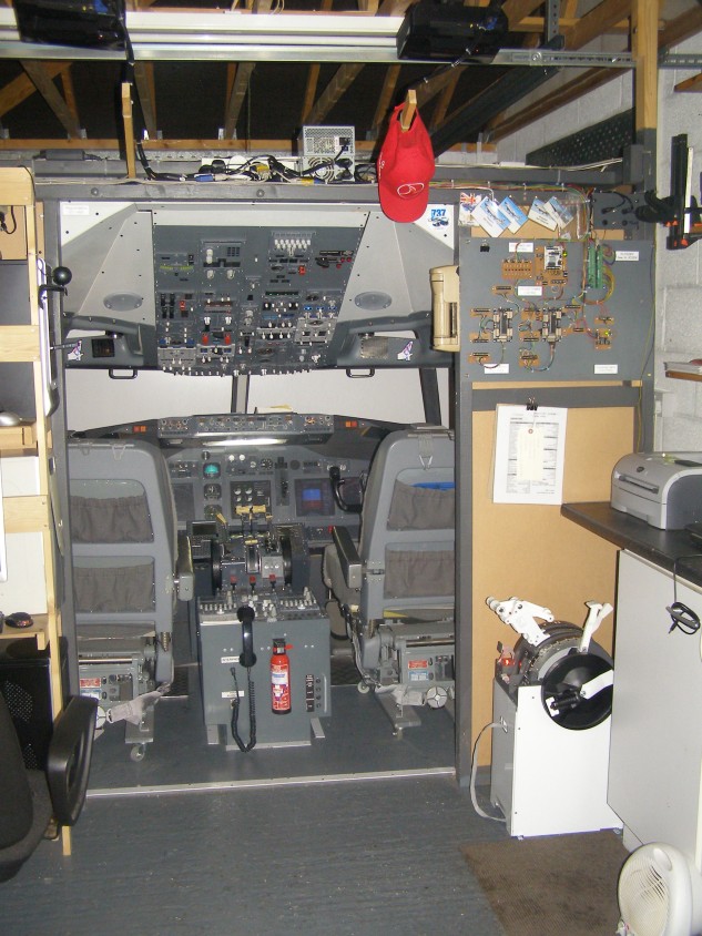
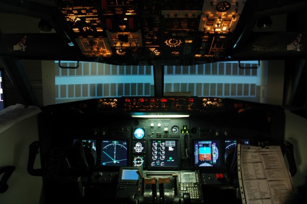
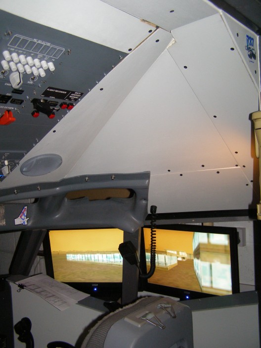
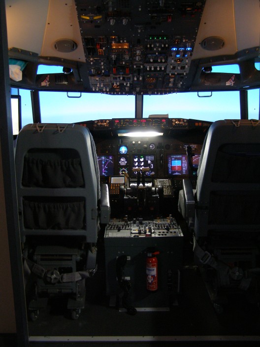
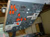
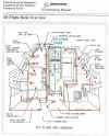
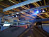
August to
October 2007.
This time was spent building the roof and Trimming Out the Flightdeck....I
was looking for a realistic shape to the roof and I just couldn't get
it right. I'm governed by the shape and size of the Eyebrow
Windows on the bottom and the size/shape of the roof at the back where
it meets the Overhead Frame. I was 'stumped', couldn't get
it right. Then purely by chance I was returning from holiday and
stood at a baggage carousel. Seen how the slats turn a
corner? BINGO, got it.
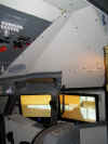

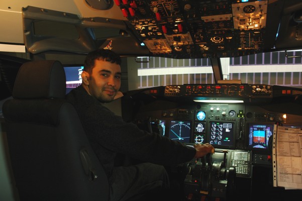
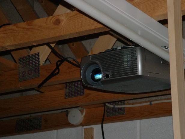
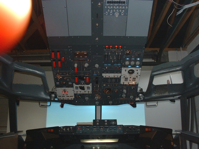
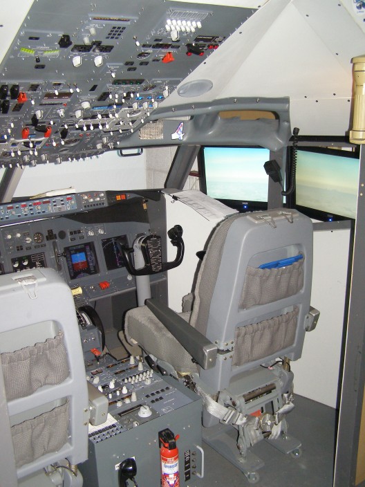
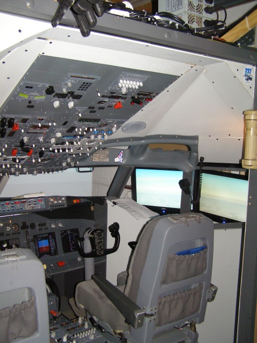
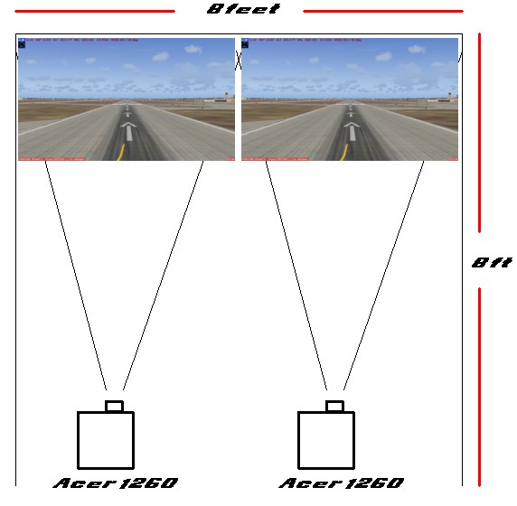
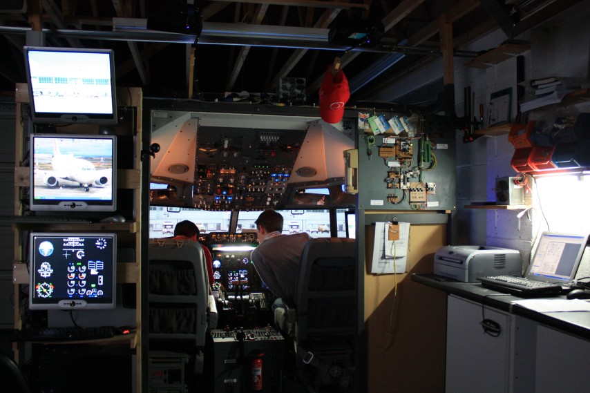
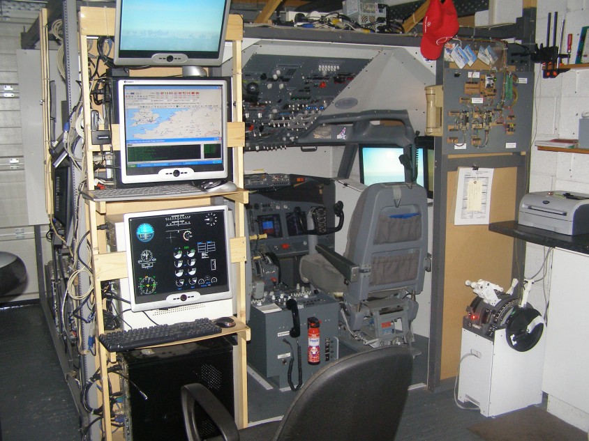
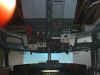
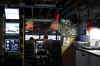
 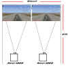 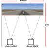  PROJECTORS
At the time of writing, I have two
ACER 1260 Projectors hooked up tru a DualHead2Go. What this
allows me to do is simply by altering the desktop properties is to
switch between either of the images seen here. Because of space
constraints, i cannot use 3 projectors to have a Left Side (at 45
degrees),CENTRE and Right Side visual system. But again given
the positioning restraints, i cant get a single projector to fill the
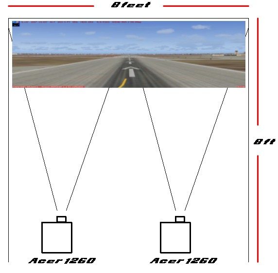
centre view. So you have to give and take a little. PROJECTORS
At the time of writing, I have two
ACER 1260 Projectors hooked up tru a DualHead2Go. What this
allows me to do is simply by altering the desktop properties is to
switch between either of the images seen here. Because of space
constraints, i cannot use 3 projectors to have a Left Side (at 45
degrees),CENTRE and Right Side visual system. But again given
the positioning restraints, i cant get a single projector to fill the
centre view. So you have to give and take a little.

|