|
First of all my apologies to Marcus at Lausitz
Aviation who's image i stole to create this masterpiece :o) -
thank you Marcus for your kindness. And I also have
to add that no two cockpits are the same for various reasons i.e.
expectations versus budget versus skill level. I did this
my way for the reasons I did and by sharing my experiences, just maybe
if you don't agree with the way I have done something, it just might
give you an idea of your own. And of course I have built
this as a fun thing and not as an obsession. The fact it turned out
pretty damn good is a bonus. I don't pretend to be a Jonathon
Richardson or a Matt Ford, but Jeez do I have fun :o)
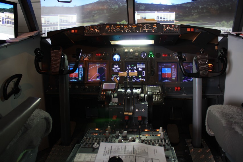
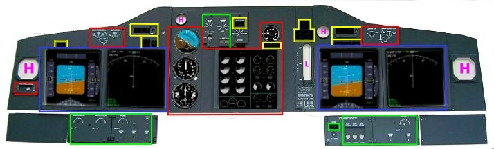
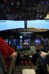
Well how do you
get it all working. In a nutshell it's not so bad if you plan it all.
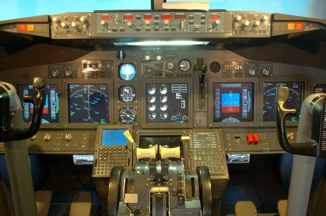
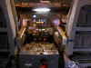
What i have done in the above diagram is to try to group everything
into colored categories. This will help me to explain where the
display comes from or where the annunciator get's it power from or
where the switch sends it signal.
If you look at the above diagram, the colour coding is as
follows......
RED = FSXPAND ( www.flyware.nl
). BLUE = PMDG ( www.precisionmanuals.com/
) GREEN = Own
Circuit
YELLOW = CPFLIGHT ( www.cpflight.com
) MAGENTA - L =LAUSITZ ( www.lausitzaviation.com
) H = HISPAPANELS ( www.hispapanels.com
) and X = Experimental that is i am playing
around with some ideas. 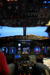
Right if you
have the rest of your life free, i'll try to explain what goes on in a
little more detail, especially the Annunciator Sources which will be at
the end of the page.  PMDG
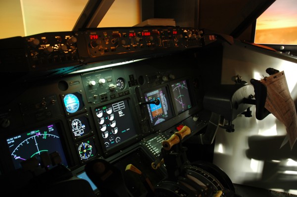
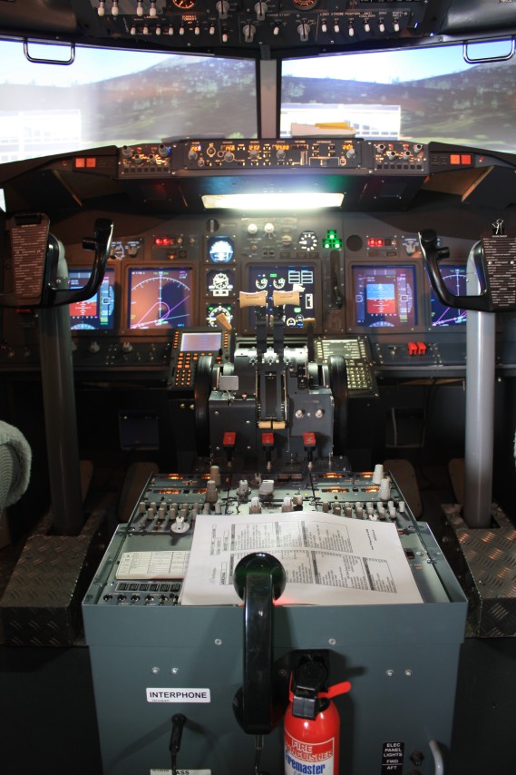
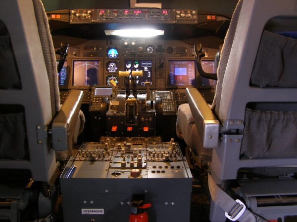
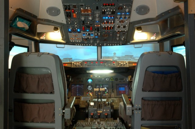
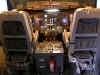
The most important source of information for the pilot is the PFD (or
Primary Flight Display) where all flight parameters are displayed. Flight Mode Annunciators,
Heading and Track Information, Rate of Climb or Descent, MCP Selection
Information - it's all contained here. Then there is the ND
(Navigation Display) where all the Navigation Map, Rose, VOR & ILS Indicators and Route
Information is displayed. The PMDG instrumentation is really
good and if you buy the Aircraft, you get it for free, now that's
value :o) PMDG
The most important source of information for the pilot is the PFD (or
Primary Flight Display) where all flight parameters are displayed. Flight Mode Annunciators,
Heading and Track Information, Rate of Climb or Descent, MCP Selection
Information - it's all contained here. Then there is the ND
(Navigation Display) where all the Navigation Map, Rose, VOR & ILS Indicators and Route
Information is displayed. The PMDG instrumentation is really
good and if you buy the Aircraft, you get it for free, now that's
value :o)
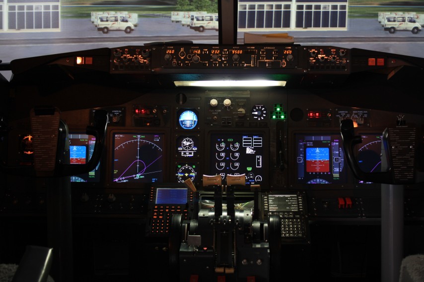
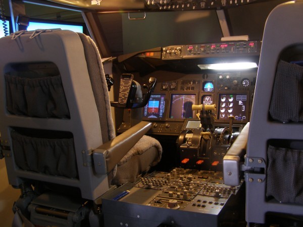
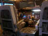
 So how did i get these displayed. I created a second cockpit
view in FS and re-wrote the PMDG panel file
for the aircraft model i use in the cockpit. I also deleted the Panel
Background bitmap because i didn't need it. This then meant that i
could close the view of the outside world on the window that contained
my panel. This panel window was moved to a second monitor
whereby adjusting the position and size of the PFD & ND gauges, i
could place them exactly where i wanted them to fit the screen frames
in my MIP. I initially was using 17" monitors, but these have
been upgraded to 19" so they fill the display frames. The
second video output is run thru a 'Y' cable
so it feeds 2 monitors, one for the captain and one for the F/O.
So how did i get these displayed. I created a second cockpit
view in FS and re-wrote the PMDG panel file
for the aircraft model i use in the cockpit. I also deleted the Panel
Background bitmap because i didn't need it. This then meant that i
could close the view of the outside world on the window that contained
my panel. This panel window was moved to a second monitor
whereby adjusting the position and size of the PFD & ND gauges, i
could place them exactly where i wanted them to fit the screen frames
in my MIP. I initially was using 17" monitors, but these have
been upgraded to 19" so they fill the display frames. The
second video output is run thru a 'Y' cable
so it feeds 2 monitors, one for the captain and one for the F/O.
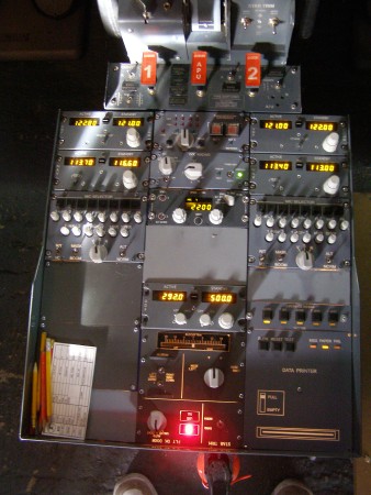
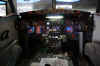
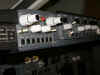
FSXPAND
The Centre EICAS display, the 3 Standby Instruments and the Rotary Flaps Gauge are all generated using FSXpand. This
is one of the best pieces of programming that i use in my setup. It is
a 2 part program developed by Gert Heijnis at www.flyware.nl
. FSXpand (the server) lives on the FS machine and
communicates with FSClient which I have on a separate networked
computer. Part of the package is a 737NG Eicas panel (ok it
doesn't fit your MIP) which can be resized and configured to fit any
monitor/screen resolution/display position. I configured
one of the panels to give me the Eicas, AI - ALT - HSI and the Rotary
Flaps Gauge. Then there is the Panel Switching function
which Gert has included in the FSC;ient Options on the client machine. This has allowed me to build 5 different
Eicas screens. Each of the 5 Screens contains the 3 standby
Instruments and the Rotary Flaps Gauge as they are displayed
irrespective of whether the Eicas is operational or
not. But the Eicas element
is different in each Screen. I have OFF - Normal - Engine
Primary with Text Annunciation - Condensed and INOP. I've simply
connected 2 Rotary Switches thru a USBKeys Card to send the key to
select the required panel. Switches are fitted to the Capt & F/O
DU Panels on the MIP
and the Rotary Flaps Gauge are all generated using FSXpand. This
is one of the best pieces of programming that i use in my setup. It is
a 2 part program developed by Gert Heijnis at www.flyware.nl
. FSXpand (the server) lives on the FS machine and
communicates with FSClient which I have on a separate networked
computer. Part of the package is a 737NG Eicas panel (ok it
doesn't fit your MIP) which can be resized and configured to fit any
monitor/screen resolution/display position. I configured
one of the panels to give me the Eicas, AI - ALT - HSI and the Rotary
Flaps Gauge. Then there is the Panel Switching function
which Gert has included in the FSC;ient Options on the client machine. This has allowed me to build 5 different
Eicas screens. Each of the 5 Screens contains the 3 standby
Instruments and the Rotary Flaps Gauge as they are displayed
irrespective of whether the Eicas is operational or
not. But the Eicas element
is different in each Screen. I have OFF - Normal - Engine
Primary with Text Annunciation - Condensed and INOP. I've simply
connected 2 Rotary Switches thru a USBKeys Card to send the key to
select the required panel. Switches are fitted to the Capt & F/O
DU Panels on the MIP
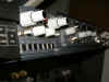
 So we can now change
the Eicas Screen to whatever we want at any phase of flight. And
the added bonus is that FSXpand will now allow multiple clients, so I
will look at repeating the above for the lower Eicas screen. ( i found
a cheap 10" monitor on e-bay :o). So we can now change
the Eicas Screen to whatever we want at any phase of flight. And
the added bonus is that FSXpand will now allow multiple clients, so I
will look at repeating the above for the lower Eicas screen. ( i found
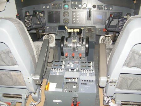
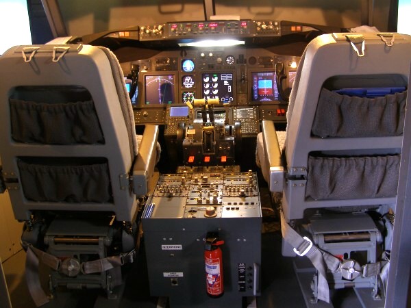
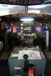
a cheap 10" monitor on e-bay :o). 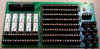 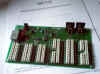 CPFLIGHT
I have the CPFlight MCPEX1. In addition to the functions
described on the MCPEX1 page, it also allows for
certain inputs and the output of certain
signals and annunciators which are detailed at the end of the page.
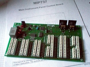
Also i have the CPFlight MIP737 Board. This is controlling all the
annunciators on the MIP very successfully and allowing me to set the
Autobrake accurately. Take a look at the
MIP737 manual HERE
to see what you can do with this board and the PMDG 737. CPFLIGHT
I have the CPFlight MCPEX1. In addition to the functions
described on the MCPEX1 page, it also allows for
certain inputs and the output of certain
signals and annunciators which are detailed at the end of the page.
Also i have the CPFlight MIP737 Board. This is controlling all the
annunciators on the MIP very successfully and allowing me to set the
Autobrake accurately. Take a look at the
MIP737 manual HERE
to see what you can do with this board and the PMDG 737.
 H
= HISPAPANELS OK I use several items from Manolo
at www.hispapanels.com
on the MIP. I H
= HISPAPANELS OK I use several items from Manolo
at www.hispapanels.com
on the MIP. I  have
the LEVEL and BALANCE Gauge just above the 3 standby Instruments and
also the Brake Pressure Gauge to the right of the Gear
Annunciators. These are both 'Dummy' Gauges to fill the Holes in
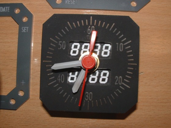
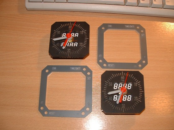
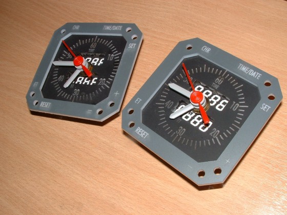
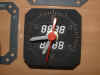
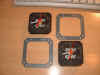
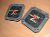
the MIP. And finally I have the Chronometers on both the
Captain and First Officer Sides. These again are dummies have
the LEVEL and BALANCE Gauge just above the 3 standby Instruments and
also the Brake Pressure Gauge to the right of the Gear
Annunciators. These are both 'Dummy' Gauges to fill the Holes in
the MIP. And finally I have the Chronometers on both the
Captain and First Officer Sides. These again are dummies  because
although you can get them up and running with Digital Readouts, I just
haven't got the time right now, maybe next
year. They are actually running as Clocks and here's
how to do it real cheap. Apart from the actual Plates, it
cost me GB£2 (about 2.80 euros each) because
although you can get them up and running with Digital Readouts, I just
haven't got the time right now, maybe next
year. They are actually running as Clocks and here's
how to do it real cheap. Apart from the actual Plates, it
cost me GB£2 (about 2.80 euros each)
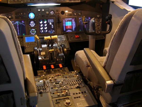
 L
= LAUSITZ The mechanical Gear lever I originally got
from the LUCHVAART HOBBY SHOP in Holland, but it has been
discontinued. Since that time, Marcus Menzel at Lausitz
Aviation L
= LAUSITZ The mechanical Gear lever I originally got
from the LUCHVAART HOBBY SHOP in Holland, but it has been
discontinued. Since that time, Marcus Menzel at Lausitz
Aviation 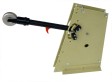 has
started production of a lever to compete with the existing products
available. I have seen this lever real close up and have
no hesitation in linking to Marcus site. He is a very dedicated,
small manufacturer of extremely high quality products. has
started production of a lever to compete with the existing products
available. I have seen this lever real close up and have
no hesitation in linking to Marcus site. He is a very dedicated,
small manufacturer of extremely high quality products.
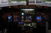
ANNUNCIATORS
I light all the MIP annunciators from the
CPFlight MIP737 board (except the Landing Gear which is lit from the
MCPEX1. The MIP737 output will be used for the Rear Overhead Gear Down
Lights). Here's what the MIP737 gives me.
BELOW GLIDESLOPE - P/Inhibit on both Sides of The cockpit.
LEADING EDGE FLAPS - In Transit and Extended.
A/P, A/T and FMC Message Annunciators on Both Sides (With Test
and Reset)
AUTOBRAKE DISARM - Set the Autobrake, LED Lights then after the
Self Test, Extinguishes
SPEEDBRAKE ARMED - Based on the Position of my Spoiler Lever
Axis.
SPEEDBRAKE EXTENDED - Lights When Spoiler is Used in Flight and
When Auto Deployed at Landing.
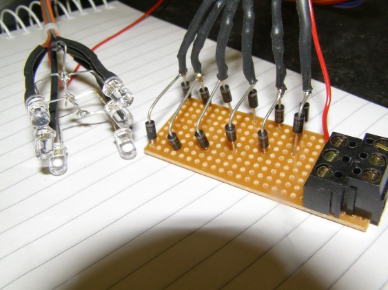
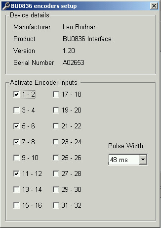
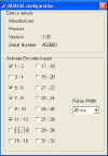
SPEEDBRAKE DO NOT ARM - Lights as advisory when instructed. BUILD
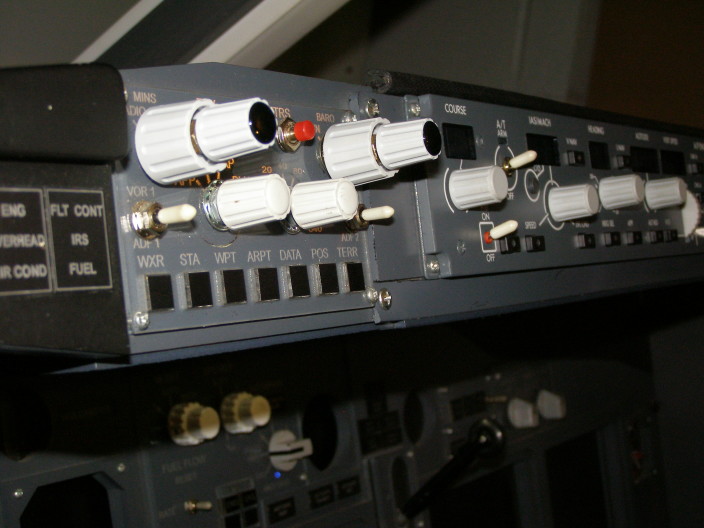
YOUR OWN EFIS Units For The PMDG Thats right. The BU0836
now supports encoders, so it has become possible to emulate the
actions of the EFIS Units in the PMDG. So i set about building a
couple. Click on the image on the left for a full explanation of 'HOW
TO DO IT' 
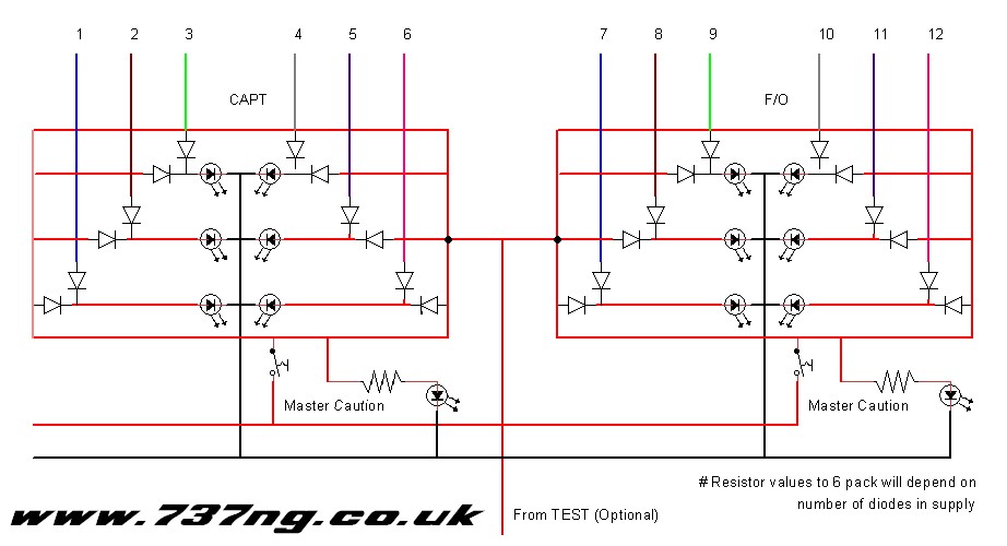
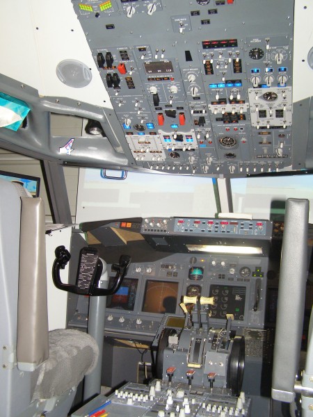
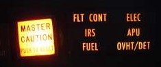 MASTER
CAUTION / RECALL / 6 PACK
We can't get this information from the PMDG, but now we have full
control of the Overhead with FSUIPC v3.81, everything has
changed. We are now able to accurately control the systems
on the overhead without seeing it. So the 6 packs are merely an
'in view' reminder that something needs your attention somewhere
else. Therefore, based on the lighting behaviour of the Overhead Panel
Annunciators, it is now possible to light some of the 6 pack
LED's. I have 6 of the 12 working right now
and i'm looking at what i can do with the remaining 6.
Further Information is available on the OVERHEAD
Page and in the left column. MASTER
CAUTION / RECALL / 6 PACK
We can't get this information from the PMDG, but now we have full
control of the Overhead with FSUIPC v3.81, everything has
changed. We are now able to accurately control the systems
on the overhead without seeing it. So the 6 packs are merely an
'in view' reminder that something needs your attention somewhere
else. Therefore, based on the lighting behaviour of the Overhead Panel
Annunciators, it is now possible to light some of the 6 pack
LED's. I have 6 of the 12 working right now
and i'm looking at what i can do with the remaining 6.
Further Information is available on the OVERHEAD
Page and in the left column.
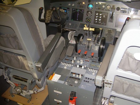
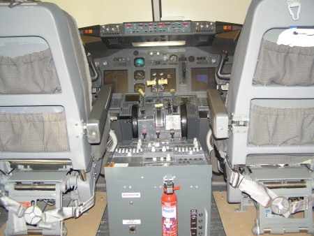
 #NOSE
WHEEL STEERING...Just a Quick Note about this (I Have Dealt
with it elsewhere). Both Pilots have a Steering Tiller,
but when they are both connected, they 'interfere' with each other. So
the simple solution was to isolate them from each other and only allow
one pot to be instructing the controller card at any one time.
So in the normal position, the Capt steers the Aircraft and in the
Alt. position the F/O has control. #NOSE
WHEEL STEERING...Just a Quick Note about this (I Have Dealt
with it elsewhere). Both Pilots have a Steering Tiller,
but when they are both connected, they 'interfere' with each other. So
the simple solution was to isolate them from each other and only allow
one pot to be instructing the controller card at any one time.
So in the normal position, the Capt steers the Aircraft and in the
Alt. position the F/O has control.
 #N1 & SPD REF Because
I'm using FSXpand, I have no way of controlling seperate NI on the
engines. However I am able to set the V Speeds manually and display
this information on the PMDG PFD. Using a dual encoder attached
to a BU0836X board and then 'Mousetrapping' the Gauge Hotspots in
FSUIPC. Result, on this control both the outer and inner sections can
be controlled by configuring the BU0836X inputs to see the encoders as
button inputs and then assigning the button inputs to the 'Mousetrapped'
macro's. If you use the PMDG EICAS, it is possible to use both
SPD REF and the N1 Set controls #N1 & SPD REF Because
I'm using FSXpand, I have no way of controlling seperate NI on the
engines. However I am able to set the V Speeds manually and display
this information on the PMDG PFD. Using a dual encoder attached
to a BU0836X board and then 'Mousetrapping' the Gauge Hotspots in
FSUIPC. Result, on this control both the outer and inner sections can
be controlled by configuring the BU0836X inputs to see the encoders as
button inputs and then assigning the button inputs to the 'Mousetrapped'
macro's. If you use the PMDG EICAS, it is possible to use both
SPD REF and the N1 Set controls 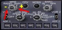 by using the same technique. by using the same technique.
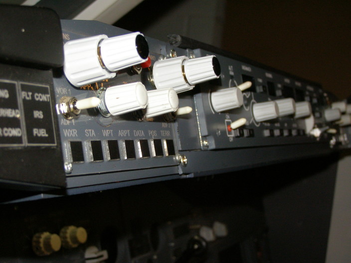
#EFIS FUNCTIONS I have now had the opportunity to
'mousetrap' all the controls on the EFIS that I wanted. FSUIPC
is much more reliable thru the BU0836X board than it is thru the
GoFlight  RP48
remote kits, so we have retrofitted new connections. Result -
brilliant. Here's a copy of my 737 MIP.mcro file with all the
mapping done for you. Just drop it into your FS2004/Modules
folder and the next time you run FS, FSUIPC will have all the switch
options available to you in the dropdown menu as 737 MIP: followed by
the option. You must have a registered version of FSUIPC to do
this v3.81 (for FS2004) or later. RP48
remote kits, so we have retrofitted new connections. Result -
brilliant. Here's a copy of my 737 MIP.mcro file with all the
mapping done for you. Just drop it into your FS2004/Modules
folder and the next time you run FS, FSUIPC will have all the switch
options available to you in the dropdown menu as 737 MIP: followed by
the option. You must have a registered version of FSUIPC to do
this v3.81 (for FS2004) or later.

Thanks
for your interest and comments, corrections and criticisms are always
welcome.
|