|
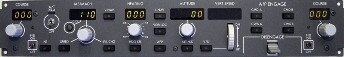
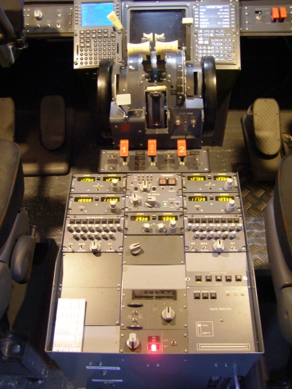
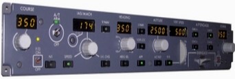
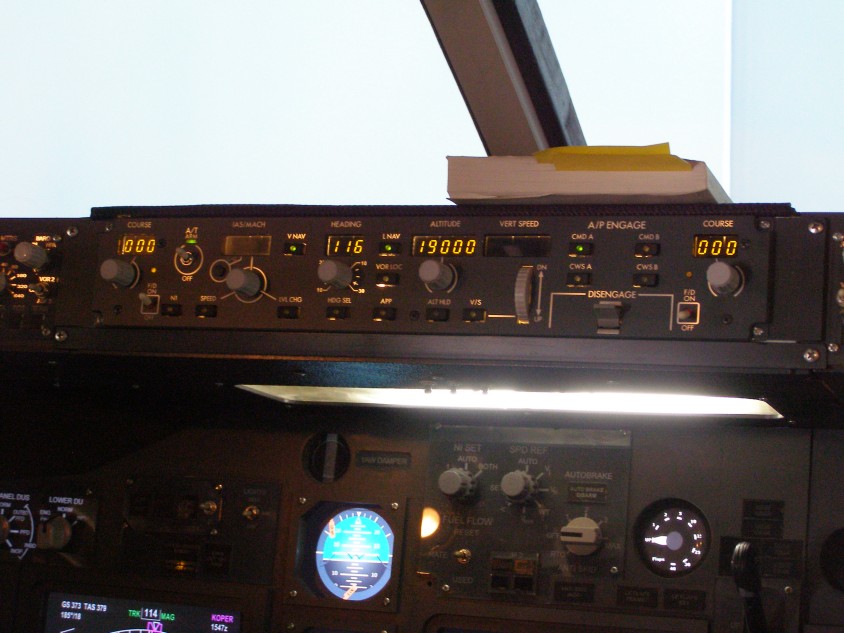
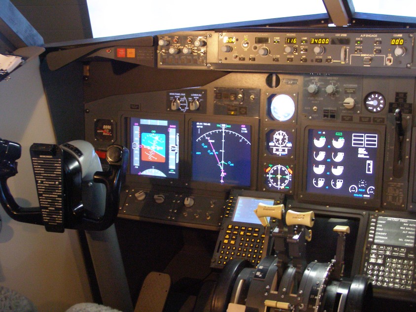
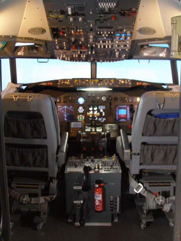
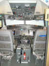
FUNCTIONS
AVAILABLE WITH THE PMDG 737
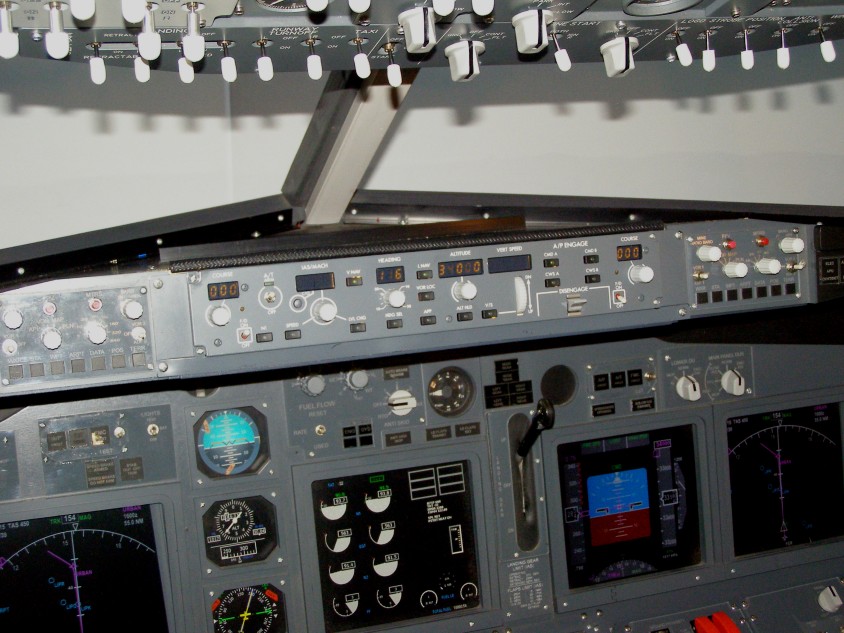
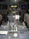 -
Nav1 Course -
Nav1 Course
- Flight Director
- Autothrottle / Speed / N1
- Master Autopilot Switch
- Speed/Mach Selector and Display
- Speed Change Over Button
- Level Change
- Heading Selector and Display
- VNAV Selector Button
- LNAV Selector Button
- VOR/LOC Selector Button
- Approach Selector Button
- Altitude/Flight Level Selector and Display
- Vertical Speed Selector Button and Display
- Vertical Speed Adjustment Control
- Command A and Command B Selector Buttons
- Control Wheel Steering A & B Selector Buttons
- Autopilot Disengage Lever
- VOR2 Course Indicator
- Now also with SPD and ALT Intervention too !
Download
The Maunual HERE
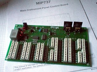
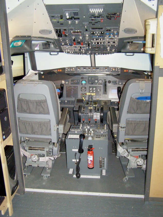
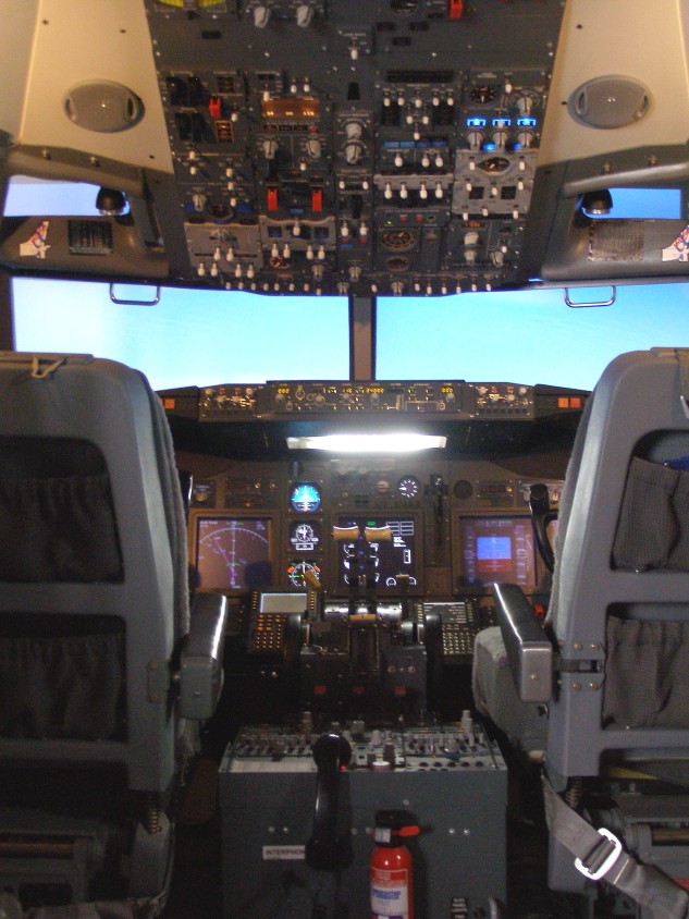
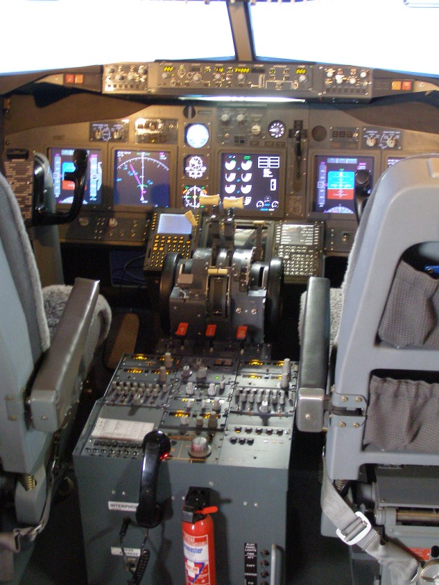
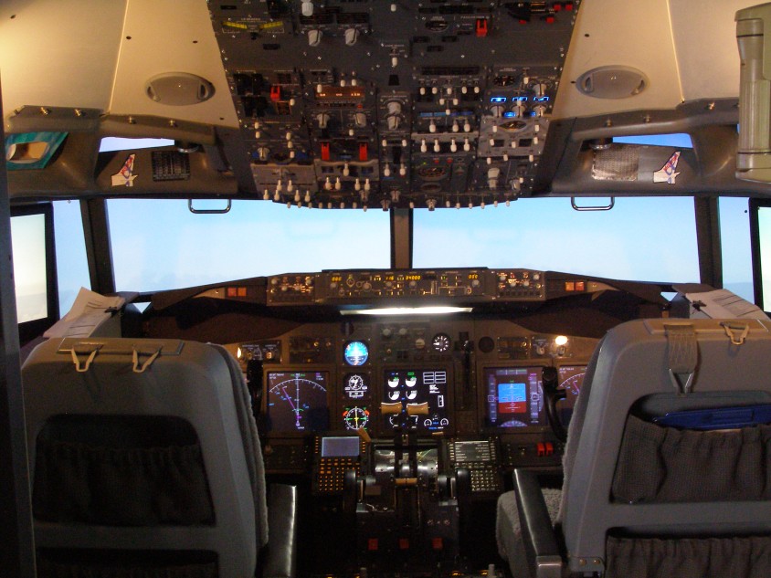
I've
also got the MIP737 Expansion Board hooked up communicating with
the PMDG taking inputs and giving me outputs to MIP
Annunciators. Functions this board gives me are:
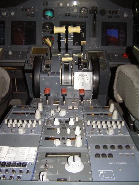
 -
Below Glideslope on both sides of MIP -
Below Glideslope on both sides of MIP
- Flaps In Transit
- Leading Edge Flaps Extended
- Gear In Transit (Red)
- Gear Down (Green)
- A/P Disconnect (and Reset) Flashing Red
- A/T Disconnect (and Reset) Flashing Red
- FMC Message (and Reset) Amber
- Autobrake
- Spoiler, Do Not Arm/Armed/Extended
Download
The Maunual HERE
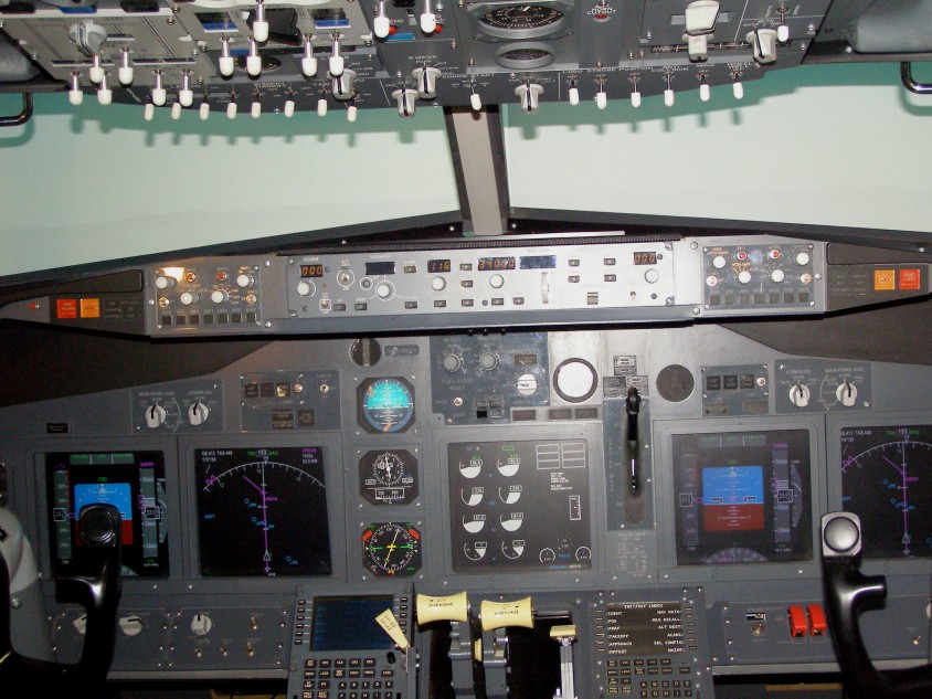
Also
connected to my MCP737 is the MCPEX1. This little beauty
offers you 64 inputs for switches, pushbuttons or
potentiometers. It also has the ability to let you assign
functions to 10 digital outputs to light annunciators when an
action occurs.
With switches & pushbuttons, using the MCP_CONF, you can
assign their action form a dropdown selection of many of the
common FS functions, send keys and get them to repeat.
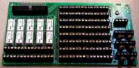
The
Digital outputs can be assigned to several of the more common FS
Functions like Gear Transit, Gear Down, Parking Brake or if
you're feeling really brave, you can write your own 'variables'
in the program. This board is is now lighting my Eng
Vales and Spar Valves Annunciators on the overhead (based on the
position of the Idle/Cutoff Levers).
-
64 Digital Assignable Inputs For Switches, Pushbuttons etc
- 10 Digital Assignable Outputs to Light Annunciators
- Analogue Inputs for Potentiometers (Throttles, Flaps etc)
Download
The Maunual HERE
|